

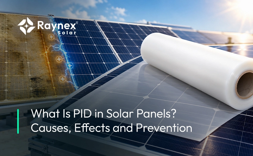
What if a solar plant looked perfect on day one, then quietly lost a fifth of its output within two years? That is what PID in solar panels can do. PID stands for potential induced degradation, and it is one of the most costly faults in modern solar modules. A survey by PI Berlin found PID in 20 solar plants in Germany. In one 10.7 MW plant in Spain, it hit 41% of the modules (PV Tech). The hard part is that PID is often invisible to the eye.
At Raynex Solar, we make the layer that sits right where PID starts: the solar encapsulant. So we look at this problem from inside the module. In this guide, we explain what PID is, why it happens, and how much yield it can cost. We also cover how to spot it, how it is tested, and which encapsulant gives the best defense. By the end, you will know exactly what to specify to keep PID out of your modules.
PID in solar panels is a loss of output caused by a large voltage gap between the solar cells and the grounded frame. That gap pushes tiny stray currents through the module. Over time, those currents move charged ions toward the cells. The ions build up at the cell surface and act like a leak. The cell then produces less current and less voltage. This is why PID is called “potential induced”: the voltage, or electric potential, is what drives the damage.
Solar modules are wired in series to form a string. Each module adds its voltage to the one before it. So a string at 1,000 or 1,500 volts has cells sitting at very different voltages from the ground. A useful way to picture it is height on a hill. A hiker high up the slope has more stored energy than one near the base, even if the climb between them is the same (pvBuero). In a string, the cells at one end sit far “below” the grounded frame. Those cells feel the strongest pull, and they suffer the most PID effect.
Not all PID is the same. The most common form in crystalline silicon modules is polarization, and it can often be undone. The first well-known case came from early SunPower modules, which lost as much as 30% of rated output in a short time (pvBuero). Changing the way the array was grounded largely reversed that loss. Other forms are permanent. Thin-film modules can suffer a type of corrosion at the front conductive layer, and that damage does not come back. Even reversible PID has a limit, because modules that degrade too far may not recover with reversal devices (Zonnefabriek). That is why we always say prevention beats repair.
To stop PID, it helps to follow the path the damage takes. Standard solar glass contains sodium. Under a strong negative voltage, positive sodium ions start to drift out of the glass. They pass through the encapsulant, then through the anti-reflective coating, and finally reach the cell (Sinovoltaics). Research has linked this pattern to a common stack: sodium-rich glass, EVA encapsulant, and a silicon nitride coating (PV Tech). Once the ions reach the cell, they collect at the surface or seep into the silicon. There they create shunts, which are short paths that let current leak away instead of flowing out of the module.
This path tells us something useful. The encapsulant is the main road between the glass and the cell. If that road conducts ions easily, PID moves fast. If it resists them, the ions stall before they do harm. In our work with module makers, this is the point we stress most. You cannot change the sun or the climate at a site, but you can choose what sits between the glass and the cell.
PID rarely has one cause. It shows up when several stress factors line up at the same time. Some come from the site, some from the module bill of materials, and some from how the system is wired. Knowing each one helps you decide where to act first. Below are the five causes we see most often.
Voltage is the engine of PID. The higher the string voltage, the bigger the gap between the cells and the grounded frame. Plants have moved from 1,000 V to 1,500 V designs to cut cable and inverter costs. That shift brings real savings, but it also raises PID risk at the ends of each string (LUBI Electronics). A module that passes in a 1,000 V system may struggle at 1,500 V. This is why the rated system voltage should always match the voltage used in PID testing.
Heat and moisture speed up PID more than any other site factor. Moisture gives ions an easy path to travel, and heat makes them move faster. Studies at Fraunhofer ISE and NREL found a strong link between PID and relative humidity above 60%, especially when paired with high temperature (PV Tech). Morning dew on the glass can also form a thin conductive film across the module surface. For plants in coastal Gujarat, Tamil Nadu, or other humid regions of India, this risk is part of daily life. You cannot change the weather, so the module itself must be built to handle it.
This is the cause we know best. Volume resistivity measures how strongly a material resists electric current flowing through it. A low-resistivity encapsulant lets ions pass more easily. A joint study by Dow and NREL compared a PID-prone EVA at 1 × 10¹³ Ω·cm with three POE grades ranging from about 9 × 10¹³ to 1 × 10¹⁶ Ω·cm (NREL/OSTI). All three POE grades fully resisted PID under 85°C, 85% humidity, and -1000 V stress. The researchers traced this to POE’s resistance to sodium ions, not only its resistivity. In plain words, the material’s chemistry matters as much as the number on the data sheet.
The glass is where the sodium comes from, so glass type plays a role. Glass with high sodium content supplies more ions that can migrate. The anti-reflective coating on the cell also matters. A well-made coating acts as a barrier that slows the flow of stray charge (LUBI Electronics). Cell type adds another layer, because n-type and p-type cells react to opposite voltage signs. A sound module design looks at all these layers together, not one at a time.
The way a system is grounded decides which cells sit at a strong negative voltage. With transformerless inverters, parts of the array sit at positive voltage and other parts at negative voltage to ground (pvBuero). For p-type modules, grounding the negative pole keeps all cells above ground and blocks the most common PID path. Not every inverter allows this, though. Poor grounding and careless string layout can therefore turn a small risk into a large one. That is why system design and module choice should be planned together.
The main effect of PID is simple: less energy from the same sunlight. What makes it dangerous is how fast and how far that loss can go. Normal solar module degradation is slow and steady. PID is neither. It can stay hidden for months and then drag an entire string down.
Most solar modules lose about 0.6% of output per year from normal aging (Zonnefabriek). PID works on a very different scale. Cells hit by PID can lose 20% to 80% of their output, and some strings have shown losses above 40% (PV Tech). In one German plant, 39% of strings showed losses of 10% to 15%. Susceptible modules may lose up to three quarters of their output within the first one or two years (Sinovoltaics). Compare that with the usual promise of 80% output after 25 years, and the gap is huge.
PID does not spread evenly across a string. In a typical p-type system, the modules closest to the negative terminal sit at the strongest negative voltage to ground. Those modules degrade first and worst, while those near the positive end may look healthy (Sinovoltaics). On an EL image, affected modules show dark cells, often near the frame edges where the distance to the grounded metal is shortest (Redalyc). This uneven pattern is a useful clue. If the output of each module drops step by step along a string, PID is a likely suspect.
Every lost kilowatt-hour is lost revenue. Take a simple example. If a 100 MW plant loses 10% of its yield to PID, it performs like a 90 MW plant for as long as the fault lasts. Lenders and investors model returns on steady output, so a sudden drop can hurt project finance and warranty claims. There are also the costs of testing, reversal devices, or module swaps. For module makers, PID returns damage brand trust, which is much harder to rebuild than a failed batch.
PID hides well, so you need the right tools to find it. A drop in plant yield is often the first hint, but many faults can cause that. The goal is to confirm PID and rule out other problems like soiling, shading, or bad connectors. Field teams usually start with simple checks and move to imaging if the signs point to PID. Here are the four methods we see used most:
Monitoring data can help too. A growing spread in MPP (peak output point) voltage between modules along a string is an early warning sign (Sinovoltaics). Still, field checks only find PID after the damage has started. The smarter move is to test for PID risk before a single module ships. That brings us to lab testing.
PID testing in the lab tells you how a module will behave years before the field does. The main reference is IEC TS 62804-1, the test method for PID in crystalline silicon modules. NREL helped shape it through round-robin tests across several labs. The base condition puts a module in a damp-heat chamber at 60°C and 85% relative humidity, with its rated system voltage applied for 96 hours (NREL). A module passes if it loses less than 5% of its output. Field results up to 28 months matched the order in which the lab test ranked module designs.
In practice, many buyers now ask for a much harder test than the base level. We often see certificates at 85°C, 85% humidity, and ±1,500 V for 96 hours. These also check wet and dry insulation resistance and look for visible defects. Some makers run the test two or three times longer to catch late-onset PID. Our advice is simple. When you review a module or an encapsulant, ask for the exact temperature, voltage, polarity, and test hours, not just the word “PID-free.” Also check that you are reading against the latest edition of the standard, since test methods are updated over time.
The best way to deal with PID is to never let it start. Prevention works on three levels: the materials inside the module, the way the module is built, and the way the system is set up. Each level closes a different door. The strongest results come when all three work together. Here is what we recommend at each level.
This is where prevention starts, and it is the cheapest point to act. The encapsulant sits on the exact path sodium ions travel, so its makeup decides how fast PID can grow. Look for high volume resistivity, low water vapor transmission, and proven test data at your system voltage. Polyolefin and ionomer films have been shown to resist PID in independent tests (PV Tech). Low-sodium or chemically strengthened glass adds another barrier on the front side. For high-voltage and glass-glass modules, we usually point clients to our POE encapsulant or EPE encapsulant. For cost-led standard modules, a PID-resistant grade of EVA encapsulant can still work well when matched with good glass and system grounding.
Good materials can still fail if the module is built poorly. Lamination must fully cure the encapsulant, because under-cured film can trap moisture and weak spots. Edge seals and frame design matter too, since PID often starts at cells near the frame. The anti-reflective coating on the cell should be tuned for PID resistance, not only for light capture. Every new bill of materials should go through PID testing before mass production. Even a small change, such as a new glass supplier, can shift results. For more on this, see our guide to common solar module lamination problems.
On site, the main tool is grounding. For p-type modules, grounding the negative pole of the array keeps all cells at a positive voltage to ground, which blocks the usual PID path (pv magazine). Where the inverter does not allow this, isolation transformers can separate the array from the grid. Another option is an anti-PID device, sometimes called a PID box or charge equalizer, that applies a reverse voltage to the array at night (Sinovoltaics).
Many string inverters now include this feature. Site choice helps a little too, since cooler, drier, and windier sites put less stress on modules. Still, system fixes add cost and need upkeep, which is why we see them as a backup to good materials, not a substitute.
The short answer is POE first, EPE second, and EVA third. Tests by several material suppliers and module makers point to the same order for reliability, and cost runs the other way, from high to low (TaiyangNews). EPE encapsulant is a three-layer film made by co-extrusion, with a POE core between two EVA skins. It was built to give much of POE’s protection at a lower cost and with easier processing (TaiyangNews). Pure POE can take longer to laminate and has a slippery surface that can let ribbons shift. EVA still bonds best to glass and costs the least. The right pick depends on cell type, system voltage, and climate.
| Factor | EVA | EPE (EVA-POE-EVA) | POE |
|---|---|---|---|
| PID resistance | Moderate; depends on the grade | High | Highest |
| Barrier to sodium ions | Lower | Good, from the POE core | Very good |
| Moisture barrier | Lower | Good | Very good |
| Acetic acid during aging | Yes, can form over time | Low when acid-free EVA skins are used | None |
| Lamination and handling | Easiest, most familiar | Easy, close to EVA | Harder; slippery surface |
| Relative cost | Lowest | Middle | Highest |
| Best fit | Cost-led mono-facial modules, lower voltage | TOPCon and bifacial modules at scale | Glass-glass, 1,500 V, humid or coastal sites |
One honest warning: not every POE is the same. A UNSW study found that some POE formulations can trigger metal corrosion in TOPCon modules, with losses of up to 55% under damp-heat testing (pv magazine). So the material family alone does not guarantee safety. Ask for PID and damp-heat data on your actual cell type before you approve any grade. Our post on what to check before approving a solar encapsulant supplier walks through that process step by step.
Often, yes, if it is caught early and is the polarization type. Most PID cases in crystalline silicon modules can be reversed, and devices like SMA’s PV Offset Box were built for this job (PV Tech). These devices work at night when the array is idle. They apply a reverse voltage that pushes the built-up ions back out of the cells. By morning, the module can produce close to normal output again (Zonnefabriek). Some plants instead ground the negative pole through a high resistance, which stops further PID but reverses existing damage less well (Sinovoltaics).
There are clear limits, though. Modules that have degraded past a certain point may not come back, even with a PID box. Damage that has turned into corrosion, such as the front-layer corrosion seen in thin-film modules, is permanent. Reversal devices also add hardware cost, draw electricity at night, and must be maintained for the life of the plant. In our view, recovery is a rescue plan, not a strategy. Choosing a PID-resistant module and encapsulant at the start costs far less than fixing a plant later.
Yes, PID still matters, but its form has changed. Many buyers assume n-type TOPCon modules are immune to PID. They are more resistant to the classic shunting type (PID-s) seen in older p-type cells. But they are open to the polarization type (PID-p), where charge builds up in the front passivation layer. A large Fraunhofer study of 20 commercial TOPCon module types rated their PID risk as similar to PERC modules, with the type shifting from PID-s to PID-p (Fraunhofer).
The numbers can be real. In a 2025 study, TOPCon modules tested at 85°C and 85% humidity lost 12.3% under positive bias and 14.3% under negative bias (ISES Solar World Congress 2025). NREL testing on one TOPCon module type found reversible PID-p only on the front face with the cells at negative voltage, and none on the rear (NREL). Light and climate change the picture too. One Trina Solar-led model for glass-glass TOPCon modules with EVA estimated 30-year PID loss at about 4% for offshore plants (pv magazine). The lesson for module makers is clear: test TOPCon modules in both polarities, and pick the encapsulant with care. We cover this in more depth in our guide to encapsulants for TOPCon solar modules.
PID in solar panels is driven by voltage, sped up by heat and humidity, and carried by ions moving from the glass to the cell. It can cut a string’s output by double digits in a short time, and it often goes unnoticed until yield reports look wrong. Field fixes like grounding changes and PID boxes can help, but they cost money and do not always work. The surest defense sits inside the module: the right glass, a sound cell coating, and above all a PID-resistant encapsulant. Even n-type TOPCon modules need this care, because PID has changed form rather than gone away.
At Raynex Solar, we manufacture EVA, POE, and EPE encapsulant sheets built for high-voltage modules and tough Indian climates. If you are planning a new bill of materials or reviewing PID test results, our team can help you match the right grade to your cell type and system voltage. Request a quote or contact our team to get samples and technical data for your next production run.
PID stands for potential induced degradation. It is a loss of output caused by a high voltage difference between the solar cells and the grounded module frame. This voltage drives stray currents and ion movement inside the module. Over time, that movement damages the cell surface and cuts the module’s output.
PID can show up much faster than normal aging. It has been seen within the first two years after installation in some plants (EPRI). In severe cases, losses can begin within days or weeks of start-up. Hot, humid sites and high-voltage strings tend to show it sooner.
Not always. “PID-free” usually means the module passed a lab test under set conditions, often with less than 5% loss. If your site runs at a higher voltage, higher heat, or higher humidity than the test, the risk can still be there. Always ask for the full test conditions, including voltage, temperature, polarity, and test hours.
PID is most common in large, high-voltage ground-mounted plants. Rooftop systems usually run at lower string voltages, so the risk is lower. Still, long strings, humid weather, and transformerless inverters can create PID conditions on rooftops too. Choosing good modules and following the maker’s grounding advice keeps that risk small.
In most tests, POE resists PID better than standard EVA because it blocks sodium ions more effectively. But not every POE grade is equal, and some formulations have caused corrosion problems in TOPCon modules. A high-quality, PID-resistant EVA can also perform well in lower-voltage, cost-led designs. The best choice depends on your cell type, voltage, climate, and test results.
The first sign is often a yield drop that monitoring cannot explain. A string check that shows falling voltage toward one end of the string is a strong clue. EL imaging can confirm it by showing dark cells, often near the frame edges. A qualified O&M team can run these tests and rule out other faults.